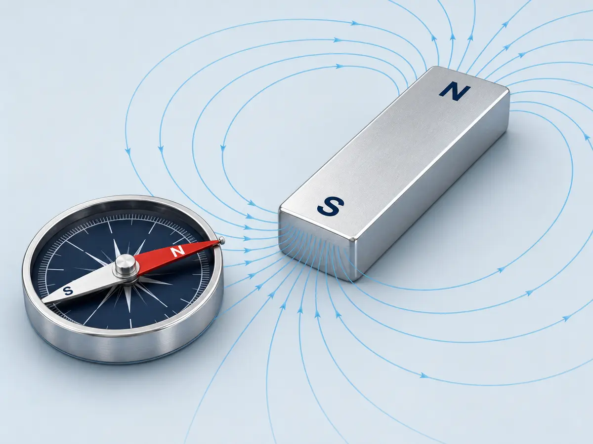
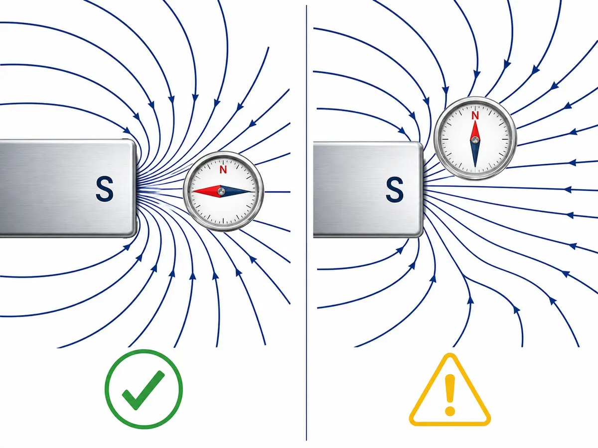
To find the north and south pole of a magnet, place a compass near one end or one face of the magnet. If the compass needle’s N-marked end points toward that surface, the tested surface is the magnet’s south pole. If the N-marked end points away from it, the tested surface is the north pole.
This works because unlike magnetic poles attract and like poles repel. For production inspection, multipole magnets or magnetic assemblies, however, a compass may not provide enough information.
Quick Answer: Which End Is North or South?
| Compass response near the magnet | Magnet pole being tested |
|---|---|
| The compass’s N-marked end points toward the magnet | South pole |
| The compass’s N-marked end points away from the magnet | North pole |
| The needle moves sideways or gives an unstable result | Reposition the compass and remove nearby magnetic interference |
| The direction changes across the same surface | The magnet may have a multipole or more complex magnetization pattern |
Test near the center of the intended pole surface rather than at an edge. Magnetic field lines curve near edges, which can make the compass needle turn sideways.
Why Does a Compass Identify Magnet Polarity?
A compass needle is itself a small magnet. Its north-seeking end is normally marked N, red or with an arrow.
The N-marked end is attracted to a magnet’s south pole and repelled by its north pole. This is the same basic rule that makes unlike poles attract and like poles repel, as explained in OpenStax Physics.
The terminology can be confusing. A compass’s north-seeking pole points approximately toward geographic north. In simple magnetic-pole terminology, the region near geographic north behaves like a magnetic south pole, even though it is commonly called the North Magnetic Pole in geographic use. The Institute of Physics explains this naming distinction.
Magnetic poles should not be described as positive and negative electrical charges. North and south describe magnetic polarity, not electric charge.
How Do You Test a Magnet with a Compass?
Follow these steps for a conventional two-pole magnet:
- Move other magnets, steel tools, motors, speakers and powered electrical equipment away from the test area.
- Place the compass on a stable, nonmagnetic surface.
- Allow the compass needle to settle.
- Slowly bring one end or face of the magnet toward the compass.
- Keep the magnet far enough away that the needle can rotate freely.
- Observe the compass’s N-marked end.
- Repeat the test on the opposite end or face.
- Mark the identified pole immediately if the application requires permanent orientation control.
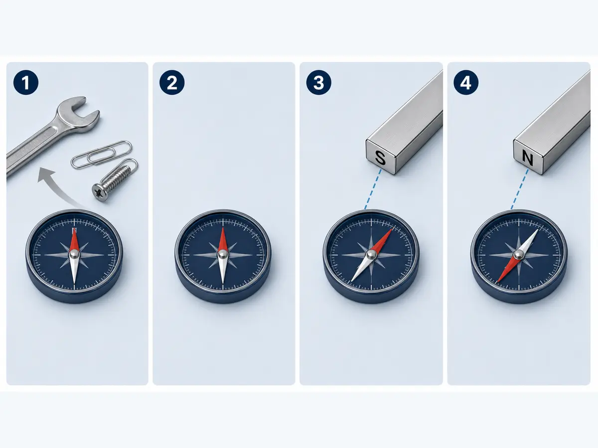
If the N-marked end points toward the tested surface, that surface is south. If it turns away, that surface is north.
Testing both sides provides a useful cross-check. For a conventional axially magnetized disc magnet, one flat face should behave as north and the opposite flat face as south.
What If the Compass Gives an Unclear Result?
| Problem | Likely reason | What to do |
|---|---|---|
| Needle snaps sharply and cannot settle | Magnet is too close or too strong | Increase the distance. |
| Needle moves sideways | Compass is near an edge where the field curves | Test near the center of the pole surface. |
| Direction changes when the compass moves across the surface | Possible multipole magnetization | Use a suitable pole detector or controlled field-mapping method. |
| Needle behaves differently in different locations | Nearby steel, magnets or electrical equipment | Clear the test area and repeat. |
| Both sides appear to give similar results | Test orientation or pole location may be incorrect | Recheck the magnetization drawing and test geometry. |
A compass is most useful for simple bar, block, disc or cylinder magnets with one north and one south pole. It is less suitable for closely spaced multipole magnets and completed magnetic assemblies.
What Other Methods Can Identify Magnet Poles?
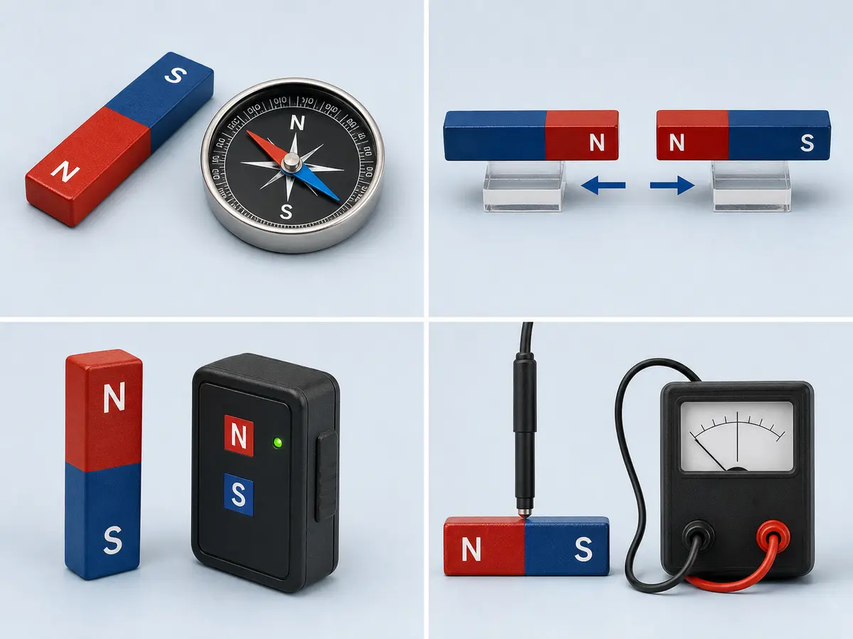
Use a Magnet with a Known Pole
A verified reference magnet can identify the polarity of another magnet.
Bring its known north pole toward the surface being tested:
- If the magnets repel, the tested surface is also north.
- If they attract and the tested part is already confirmed to be a magnet, the tested surface is likely south.
Repulsion is the clearer result because unmagnetized ferromagnetic steel can also be attracted to either pole of a permanent magnet. Attraction alone therefore cannot prove that an unknown metal part has a particular magnetic polarity.
Use an Electronic Pole Identifier
An electronic pole identifier may display N or S when placed near a magnetic surface. It can be faster than a compass when checking many simple magnets.
However, sensing distance, display convention and suitable field range depend on the device. Check the detector against a known reference pole and follow its manual before using it for receiving or production inspection.
For closely spaced poles, confirm that the sensor area is small enough to resolve the required pole pattern.
Use a Gauss Meter or Hall Probe
A gauss meter measures magnetic flux density at the probe location. A signed reading may also indicate field direction, but only when the following are known:
- Probe sensing direction.
- Instrument sign convention.
- Probe orientation.
- Measurement location.
- Distance or air gap from the magnet.
- Zeroing and functional-check procedure.
Do not assume that a positive reading always means north or a negative reading always means south. The result depends on how the manufacturer defines the probe’s positive sensing direction.
A gauss meter is more useful than a compass when the buyer must verify both field direction and a specified magnetic-field value. The test conditions must be defined if the reading is used for acceptance.
Can You Use a Smartphone?
A smartphone magnetometer can demonstrate changes in magnetic-field strength and direction, but phone sensors, coordinate systems and apps vary.
It may be useful for a basic experiment, but it should not be the sole method for production inspection, batch acceptance or a safety-related assembly decision.
Can You Suspend the Magnet Freely?
A lightweight bar magnet suspended so that it can rotate freely will normally align approximately with Earth’s magnetic field. The end pointing toward geographic north is called the north-seeking pole.
This method is simple but sensitive to nearby metal, other magnets, air movement and suspension friction. It is better suited to demonstration than controlled inspection.
Which Methods Do Not Reliably Identify North and South?
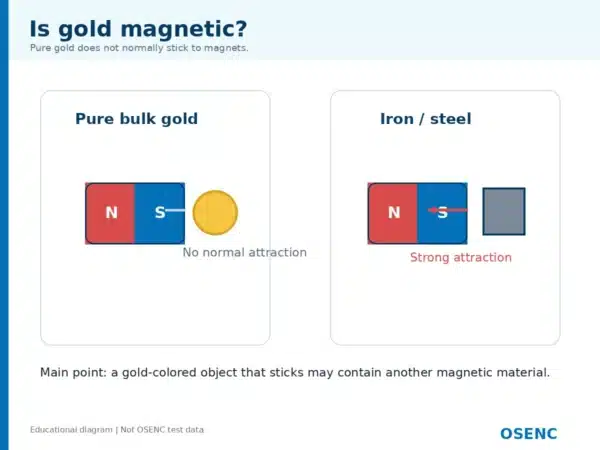
Steel Attraction
A steel object may be attracted to either pole. It cannot tell you whether the tested surface is north or south.
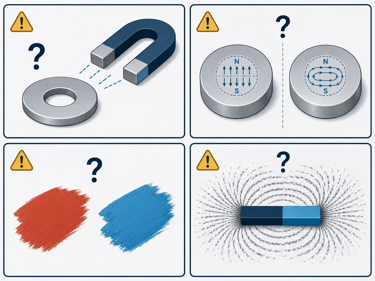
Magnet Color
Red and blue paint are common educational conventions, but there is no universal rule that every red end is north or every blue end is south.
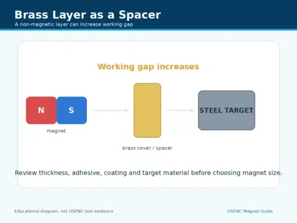
Plating color also does not indicate magnet polarity. Nickel, zinc, epoxy and other coatings are selected for protection or application requirements, not as a universal pole code.
Magnet Shape
The shape of a magnet does not prove its magnetization direction. Two disc magnets with the same dimensions may be magnetized axially, diametrically or in a custom multipole pattern.
Always confirm the magnetization direction separately.
Iron Filings and Magnetic Viewing Film
Iron filings can show the general magnetic-field pattern, but they do not label a region as north or south.
Standard magnetic viewing film can help reveal pole boundaries and field patterns, but it should not automatically be treated as an N/S identifier. Some specialized indicator products operate differently, so their documentation must be checked.
How Does Magnetization Direction Affect Pole Location?
Pole location depends on magnetization direction, not only on the magnet’s physical shape.
| Magnetization pattern | Typical pole location | Important limitation |
|---|---|---|
| Axial | Opposite flat faces | Common for discs, rings and cylinders, but the drawing must still confirm it. |
| Diametrical | Opposite sides across the diameter | Common for some cylinders, sensor magnets and rotors. |
| Radial | In some designs, inner and outer circumferences | Segmented and multipole rings may use different orientation patterns. |
| Multipole | Alternating pole regions on one or more surfaces | Pole count, pole pitch and sequence require a drawing or field map. |
| Custom magnetic assembly | Determined by the individual magnet layout | The external field may not match the apparent orientation of one visible magnet. |
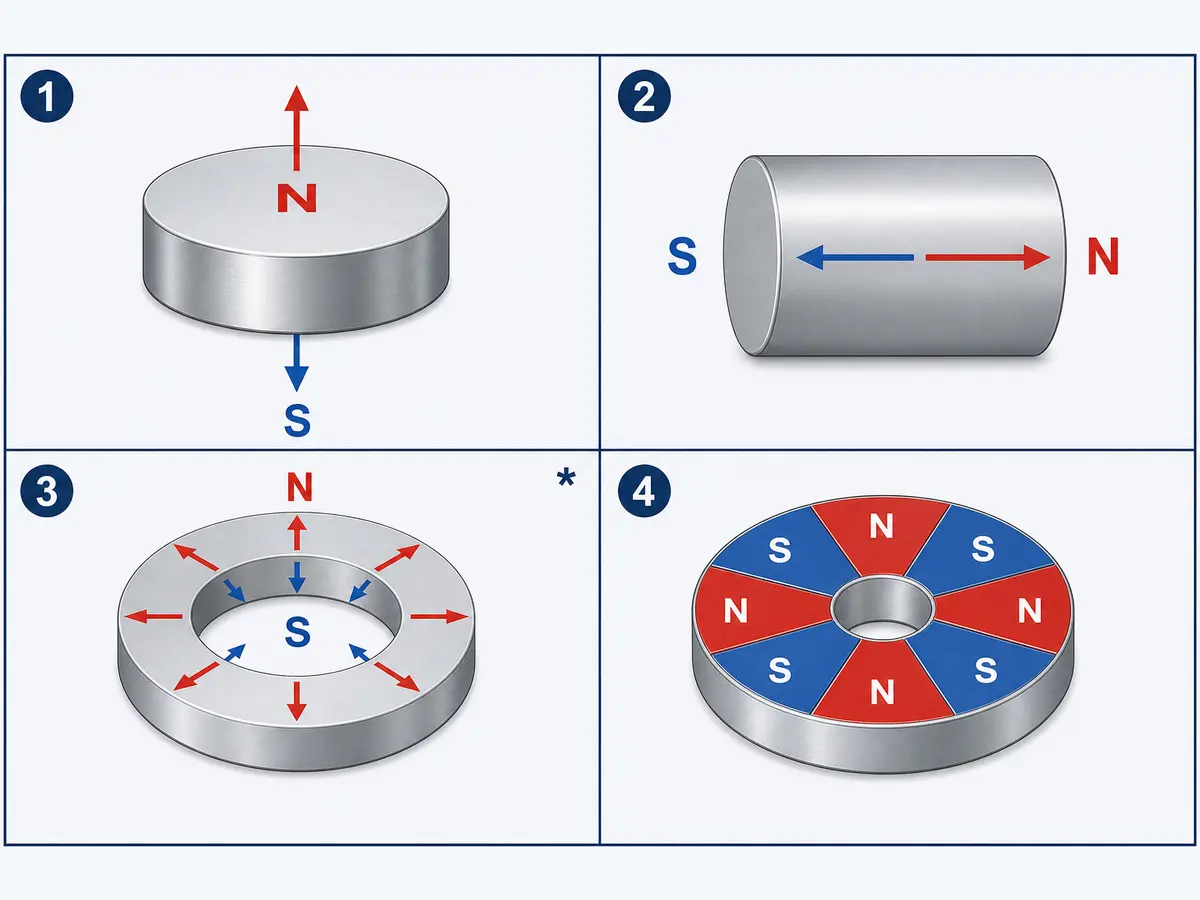
A ring magnet is not automatically radially magnetized. Many ring magnets are axially magnetized, with north and south on the two flat annular faces.
For custom neodymium magnets, the drawing should specify the magnetization direction rather than relying on shape names such as disc, ring or block.
Why Does Magnet Polarity Matter in an Assembly?
For a magnet simply attracting an unmagnetized steel plate, north versus south may not affect the basic holding function.
Polarity becomes important when the magnet interacts with:
- Another permanent magnet.
- A Hall sensor or magnetic encoder.
- A motor rotor or stator.
- A magnetic coupling.
- A multipole ring.
- A Halbach array.
- A polarity-sensitive detection system.
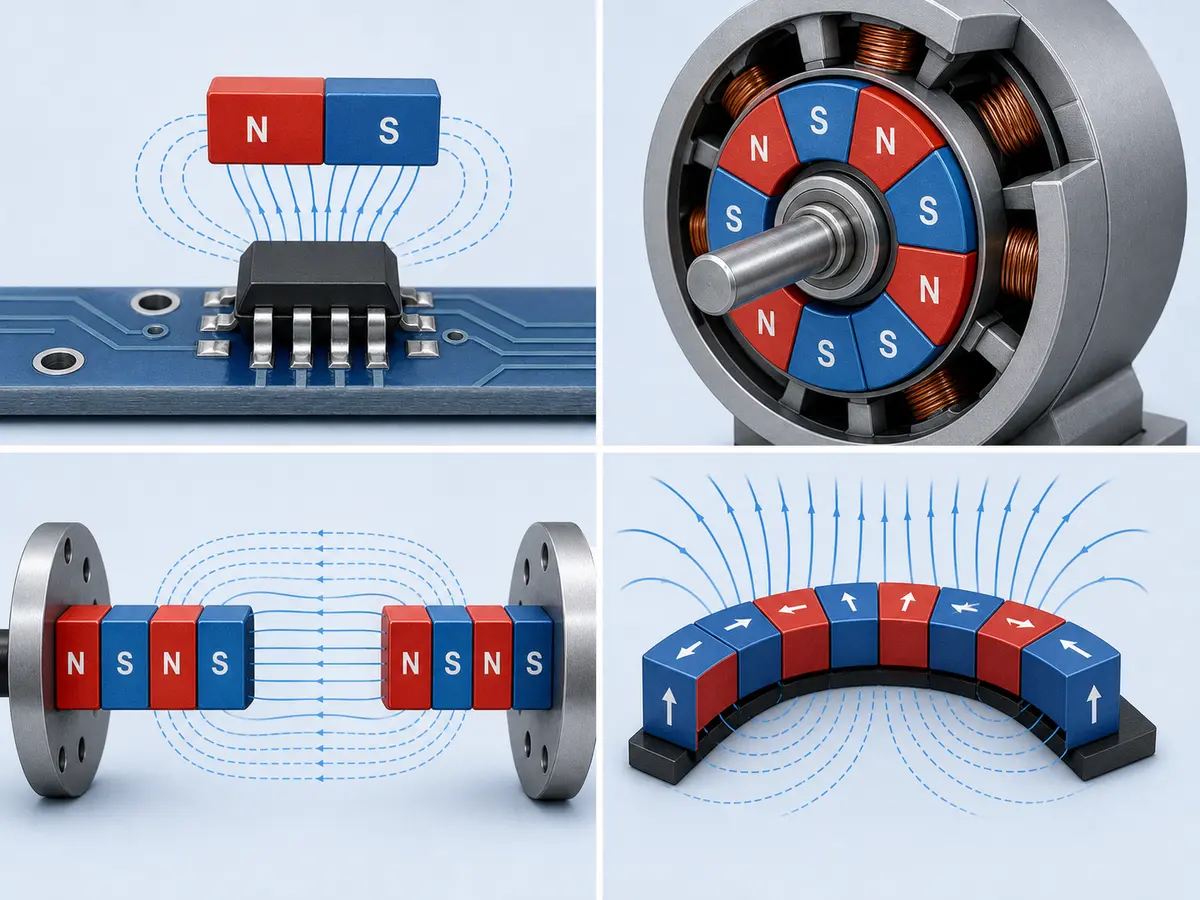
Installing one magnet in the wrong direction can change attraction into repulsion, reverse a sensor response or disrupt the intended field pattern.
For these applications, the requirement should not be written only as “magnetized.” The drawing or specification should define the required direction, pole layout and acceptance method.
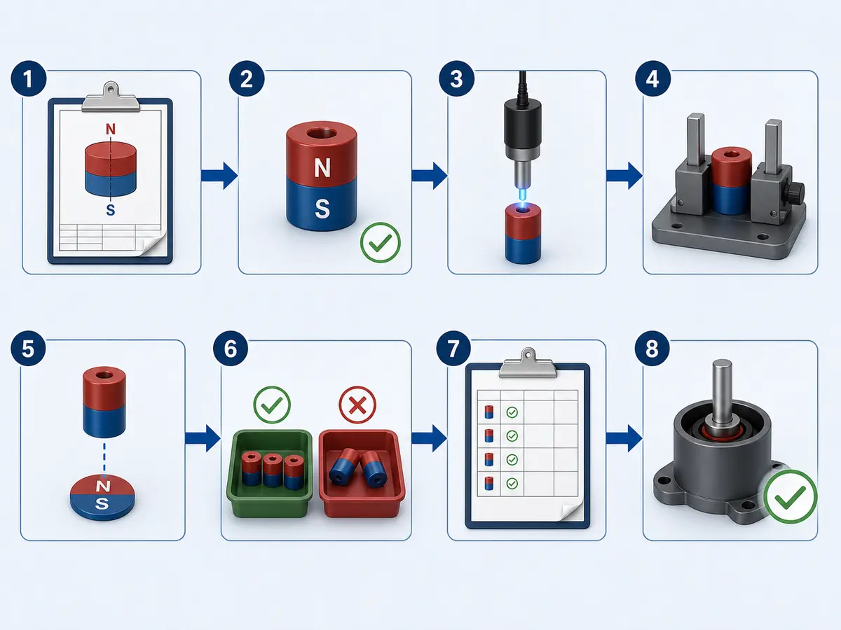
How Should Buyers Verify Polarity in a Batch?
- Confirm the approved drawing revision.
- Identify whether acceptance concerns N/S identity, pole sequence, field value or functional response.
- Establish a verified master magnet or approved reference.
- Select a detector suitable for the pole size and spacing.
- Define the test position, orientation and distance.
- Use a fixture when repeatable positioning matters.
- Mark or separate inspected parts to prevent mixing.
- Record the results and any nonconforming pieces.
- Use orientation features or mistake-proofing during assembly where possible.
- Complete a functional check when polarity alone does not prove assembly performance.
A useful inspection record may include:
- Part number.
- Drawing revision.
- Required pole or pole sequence.
- Test location.
- Fixture orientation.
- Instrument or reference identification.
- Result.
- Date and inspector.
If a magnetic-field value is an acceptance criterion, also define the probe, air gap, measurement direction and permitted range. A documented plan can also support communication with the supplier’s quality management team.
What Exactly Should the Acceptance Criterion Be?
“Check magnet polarity” may be too vague for a production drawing or purchase order.
Choose the acceptance basis that matches the application:
| Acceptance basis | Suitable when |
|---|---|
| N/S identity only | A simple magnet must be assembled in the correct direction. |
| Pole count and sequence | A multipole ring, rotor or encoder magnet must follow a defined pattern. |
| Magnetic-field reading | A specified field component must be measured at a controlled location and gap. |
| Field map | Pole boundaries or field distribution matter across a surface or working area. |
| Functional response | The magnet must operate correctly with a sensor, motor, coupling or complete assembly. |
A polarity test does not automatically prove that the magnetic field is strong enough for the application. Likewise, one surface-field reading may not prove performance at the actual working gap.
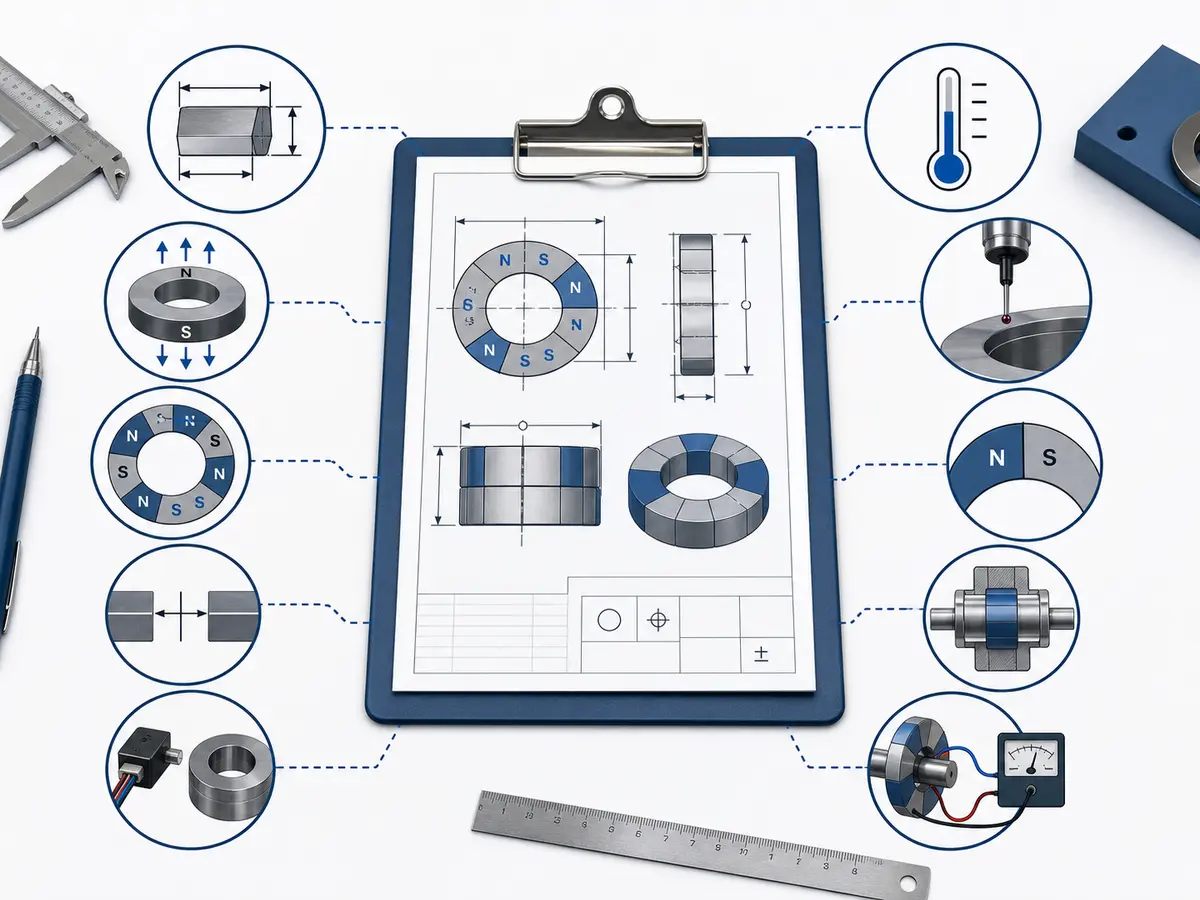
What Information Should Be Included in an RFQ?
For a custom or polarity-sensitive magnet, provide:
- Magnet material and grade, if already selected.
- Complete dimensions and tolerances.
- Magnetization direction.
- Number of poles.
- Required pole sequence or pole pitch.
- Pole-marking location.
- Assembly orientation.
- Working distance or air gap.
- Mating magnet, steel component or sensor information.
- Operating temperature.
- Required inspection method.
- Whether acceptance is based on N/S identity, field value, field map or functional response.
- Whether the pole mark must remain visible after assembly.
If the magnetization pattern is difficult to show in words, include a marked drawing, sketch or sample.
OSENC can review drawings, sketches, samples and application requirements to help clarify the magnetization direction, pole layout and suitable verification method. Magnetic simulation may support design evaluation for complex assemblies, but physical inspection is still needed to confirm actual production parts.
Frequently Asked Questions
Is the Red End of a Magnet Always North?
No. Red and blue are common teaching colors, but they are not universal manufacturing standards. Verify the pole instead of relying on color.
Can Iron Filings Show Which Pole Is North?
Iron filings show a magnetic-field pattern but do not identify which region is north or south.
Can a Steel Object Identify Magnet Polarity?
No. Steel can be attracted to either pole and therefore cannot distinguish north from south.
Where Are the Poles on a Ring Magnet?
It depends on the magnetization direction. An axially magnetized ring usually has poles on its two flat faces. Some radial designs may have opposing inner and outer circumferences, while multipole rings contain several alternating pole regions.
Can a Gauss Meter Tell North from South?
It can indicate field direction when the probe orientation and instrument sign convention are known. A positive or negative number has no reliable N/S meaning without those conditions.
Can a Phone Identify Magnet Poles?
A phone may demonstrate changes in the magnetic field, but it is not a reliable production inspection tool because sensors and apps vary.
Does Each Piece of a Broken Magnet Have North and South Poles?
Yes. Breaking an ordinary permanent magnet creates smaller pieces that each still behave as magnets with north and south poles. It does not create an isolated magnetic pole.
Need Help Confirming a Custom Magnetization Pattern?
For a simple two-pole magnet, a compass or verified reference magnet may be enough. For multipole magnets, rotors, sensor magnets, magnetic couplings or other assemblies, specify the pole pattern and verification method before production.
OSENC can review your drawing, sketch, sample or application requirements to help clarify the magnetization direction and inspection approach.
Discuss Your Magnetization Requirements