







OSENC produkuje na zamówienie magnesy rurowe ze spiekanego NdFeB zgodnie z rysunkiem, z kontrolowanymi średnicami zewnętrzną i wewnętrzną, długością, powłoką oraz sposobem magnesowania, przeznaczone do zastosowań na wałach, w czujnikach, silnikach i zespołach cylindrycznych.
Nasz obecny zakres produkcyjny obejmuje średnice zewnętrzne 1,5–60 mm, średnice wewnętrzne 0,4–50 mm oraz długości 0,3–120 mm. Prosimy przesłać wymiary: średnica zewnętrzna × średnica wewnętrzna × wysokość, kierunek magnesowania oraz warunki pracy, a przed przygotowaniem wyceny zweryfikujemy pełną geometrię.
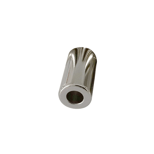
Magnes rurowy wygląda na prosty element, dopóki otwór, ścianka, powłoka i obwód magnetyczny nie muszą prawidłowo współpracować w jednym zespole. Kontrolujemy element jako jeden gotowy komponent, zamiast traktować każdą specyfikację oddzielnie.
Wytwarzamy średnicę zewnętrzną, otwór i długość całkowitą jako jedną spójną geometrię, uwzględniając wpływ powłoki na krytyczne wymiary pasowania.
Analizujemy średnicę wewnętrzną, grubość ścianki i długość łącznie, ponieważ geometria sprawdzająca się w przypadku krótkiego pierścienia może nie pozostać praktyczna w przypadku długiej rury.
Dopasowujemy kierunek biegunów do rzeczywistego obwodu magnetycznego, zamiast dobierać kierunek magnesowania wyłącznie na podstawie kształtu rury.
Określamy zakres kontroli wymiarów, powłoki i parametrów magnetycznych zgodnie z wymaganiami odbiorowymi zawartymi na Państwa rysunku.
| Element | Dostawy magnesów rurowych OSENC | Co uwzględnić w zapytaniu ofertowym |
|---|---|---|
| Materiał | Spiekane magnesy NdFeB | Klasa lub docelowy parametr magnetyczny |
| Geometria | Wydłużony magnes cylindryczny z prostym otworem przelotowym | Średnica zewnętrzna × średnica wewnętrzna × wysokość |
| Średnica zewnętrzna | 1,5–60 mm | Wymagana końcowa średnica zewnętrzna i pasowanie |
| Średnica wewnętrzna | 0,4–50 mm | Wymagana końcowa średnica otworu po nałożeniu powłoki |
| Długość | 0,3–120 mm | Całkowita długość wyrobu gotowego |
| Klasy | Gatunki N35–N55 oraz rodziny klas temperaturowych analizowane pod kątem zastosowania | Temperatura pracy |
| Magnesowanie | Określone na rysunku | Orientacja biegunów, położenie czujnika lub magnetycznie czynne powierzchnie robocze |
| Powłoka | Warianty z powłoką niklową, cynkową, epoksydową i na bazie Parylene | Środowisko pracy i końcowe pasowanie |
Neodymowy magnes tulejowy należy zastosować, gdy konstrukcja wymaga cylindrycznego magnesu NdFeB z otworem przelotowym zapewniającym miejsce na wał, tuleję, prowadnicę, przewód, element złączny lub wewnętrzny zespół.
W porównaniu z pełnym walcem otwór tworzy powtarzalny interfejs mechaniczny. W porównaniu z krótkim pierścieniem dłuższy korpus zapewnia większą długość osiową na potrzeby montażu. Konstrukcja działa prawidłowo, gdy otwór, geometria ścianki, kierunek biegunów i rzeczywista szczelina robocza są kontrolowane łącznie.
W przypadku magnesów rurowych OSENC stosuje się oznaczenia: D = średnica zewnętrzna, d = średnica wewnętrzna oraz H = wysokość całkowita / długość.
Przykład: D10 × d7 × H30 mm oznacza średnicę zewnętrzną 10 mm, średnicę wewnętrzną 7 mm i długość całkowitą 30 mm.
W przypadku tulei z otworem o stałej średnicy nominalna promieniowa grubość ścianki wynosi (D − d)/2. Teoretycznej wykonalności nie oceniamy wyłącznie na podstawie grubości ścianki. Analizujemy łącznie średnicę zewnętrzną, średnicę wewnętrzną, wysokość, gatunek materiału, naddatek na szlifowanie, powłokę i wykonanie krawędzi.
Jeśli tuleja współpracuje z wałem lub pracuje w pobliżu czujnika, wymagania dotyczące pasowania, współosiowości lub bicia należy podać bezpośrednio na rysunku.
| Parametr | Zakres OSENC | Kluczowe aspekty techniczne |
|---|---|---|
| Średnica zewnętrzna | 1,5–60 mm | Końcowa średnica zewnętrzna, manipulowanie elementem i obwód magnetyczny |
| Średnica wewnętrzna | 0,4–50 mm | Pasowanie otworu, grubość ścianki i grubość powłoki |
| Wysokość × szerokość × głębokość | 0,3–120 mm | Duża długość i cienkie ścianki utrudniają obróbkę oraz manipulowanie elementem |
| Kierunek ułożenia biegunów | Do 120 mm | Kierunek biegunów określony na zatwierdzonym rysunku |
Teoretycznych zakresów średnicy zewnętrznej, średnicy wewnętrznej i H nie można dowolnie łączyć. Długie tuleje, małe otwory i cienkie ścianki zwiększają trudność obróbki, wykonania krawędzi i manipulowania elementem. Prosimy przesłać pełny zestaw wymiarów: średnica zewnętrzna × średnica wewnętrzna × H. Geometria zostanie przeanalizowana przed przekazaniem rysunku produkcyjnego do realizacji.
Dobieramy sposób magnesowania na podstawie roboczego obwodu magnetycznego, a nie wyłącznie kształtu magnesu rurowego. Prosimy zaznaczyć na rysunku wał, położenie czujnika, szczelinę powietrzną, współpracujący element stalowy lub wymagany kierunek pola.
Stosujemy magnesowanie osiowe, gdy główne pole magnetyczne ma działać przez dwie pierścieniowe powierzchnie czołowe.
Stosujemy magnesowanie średnicowe, gdy pole ma działać w poprzek korpusu cylindrycznego, w tym w odpowiednich konstrukcjach obrotowych i układach czujnikowych.
W przypadku wymagań dotyczących magnesowania promieniowego lub wielobiegunowego przed przygotowaniem wyceny analizujemy stosunek OD/ID, długość osiową, klasę magnesu i oprzyrządowanie.
OSENC może przeanalizować N35–N55 oraz rodziny klas temperaturowych, w tym M, H, SH, EH i AH dla magnesów rurowych wykonywanych na zamówienie.
Dobieramy klasę magnesu z uwzględnieniem średnicy zewnętrznej, średnicy wewnętrznej, grubości ścianki, temperatury pracy i wymaganego obwodu magnetycznego. Wyższa klasa nie zawsze jest lepszym wyborem, jeśli geometria lub wymagania temperaturowe wskazują na inne rozwiązanie.
Prosimy podać temperaturę pracy i wymagany parametr magnetyczny. Dopasujemy klasę do gotowego elementu, zamiast traktować ją jako odrębną specyfikację.
OSENC oferuje niklowe, cynkowe i, epoksyd oraz Parylenna bazie żywicy epoksydowej opcje powłok dla niestandardowych magnesów neodymowych.
W przypadku magnesu rurowego wybór powłoki wpływa nie tylko na odporność korozyjną. Grubość powłoki zmienia gotową średnicę zewnętrzną, gotową średnicę wewnętrzną oraz rzeczywisty luz montażowy.
Jeśli otwór ma pasować na wał lub tuleję, należy określić wymaganą gotową średnicę wewnętrzną po naniesieniu powłoki. Jako docelowy wymiar produkcyjny przyjmujemy wymiar gotowego elementu z zatwierdzonego rysunku.
W przypadku niestandardowych magnesów z powłoką epoksydową potwierdzony przez OSENC zakres grubości powłoki epoksydowej wynosi 15–40 μm. Przed zwolnieniem do produkcji potwierdzamy, czy wymagana geometria rurowa i tolerancja gotowego elementu są odpowiednie.
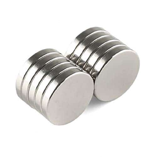
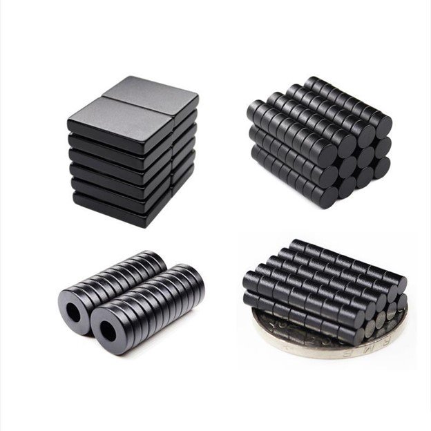
W przypadku konstrukcji silników i elementów mocowanych na wale analizujemy jednocześnie pasowanie otworu, geometrię wirnika, kierunek namagnesowania biegunów, szczelinę powietrzną i temperaturę pracy.
W zastosowaniach czujnikowych prześlij lokalizację czujnika, kierunek odczytu i roboczą szczelinę powietrzną. Analizujemy geometrię magnesu rurowego i magnesowanie w obszarze położenia detekcji.
W projektach siłowników dobieramy magnes rurowy do pręta, prowadnicy, kierunku ruchu i obwodu magnetycznego.
Stosujemy geometrię z otworem przelotowym, gdy magnes musi być zamontowany wokół wału, tulei, przewodu, prowadnicy lub elementu wewnętrznego, który blokowałby lity walec.
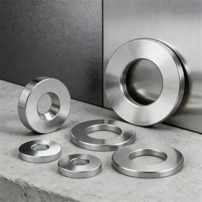
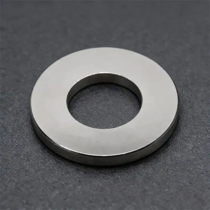
Rysunek określa kluczowe wymagania. Plan kontroli opracowujemy wokół wymiarów i właściwości magnetycznych, które warunkują działanie zespołu.
| Kontrolę | Co sprawdzamy | Dlaczego ma to znaczenie |
|---|---|---|
| OD / ID / H | Wymiary końcowe po obróbce i nałożeniu powłoki | Pasowanie na wale i luz montażowy |
| Otwór i krawędź | Stan otworu, wykruszenia i uszkodzenia krawędzi | Niezawodność cienkich ścianek i ochrona podczas montażu |
| Powłoka | Pokrycie, stan powierzchni i określona grubość | Ochrona przed korozją i końcowe dopasowanie |
| Kierunek biegunów | Kierunek magnesowania | Prawidłowy obwód magnetyczny |
| Pomiar wartości Gaussa | Określone miejsce pomiaru, orientacja i odległość | Powtarzalne kryterium odbioru parametrów magnetycznych |
| Geometria specjalna | Współosiowość lub bicie, jeśli określono | Zespoły wirujące lub pracujące z małą szczeliną |
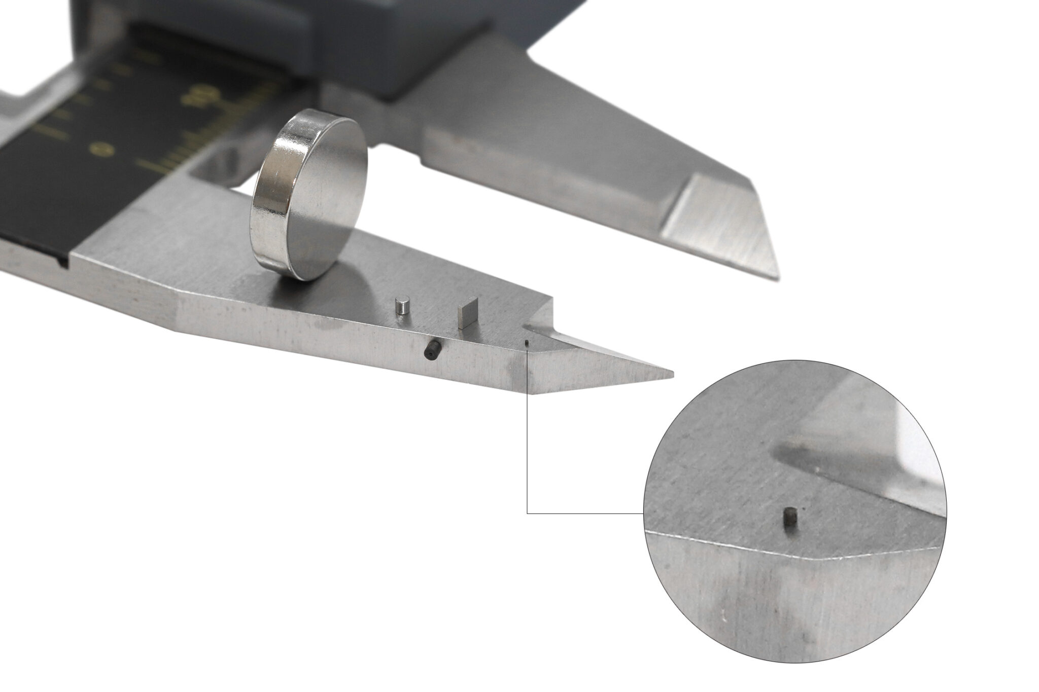

Wartość w gausach jest miarodajna tylko wtedy, gdy ustalone są wymiary i klasa magnesu, kierunek biegunów, położenie i orientacja sondy oraz odległość robocza. Jeśli projekt obejmuje kryterium odbioru parametrów magnetycznych, prześlij nam miejsce pomiaru i szczelinę roboczą, abyśmy mogli określić warunki badania przed rozpoczęciem produkcji.
Najlepiej przesłać kompletny rysunek, ale na początek wystarczą OD × ID × H oraz opis zastosowania.
Aby rozpocząć rozmowę, nie potrzebujesz kompletnego rysunku wykonawczego. Prześlij nam znane już wymiary, zastosowanie i kierunek roboczy pola magnetycznego.
Przed przygotowaniem oferty i próbek przeanalizujemy geometrię magnesu rurowego, klasę magnesu, powłokę, kierunek magnesowania i wymagania dotyczące kontroli jako parametry jednego gotowego elementu.
Prześlij wymagania dotyczące magnesu rurowego| Produkt | Co to jest | Najlepsze dopasowanie | Główne dane do zapytania ofertowego |
|---|---|---|---|
| Neodymowy magnes rurowy | Wydłużony element ze spiekanego NdFeB z prostym otworem przelotowym. | Wały, czujniki, silniki, siłowniki i cylindryczne zespoły OEM. | Średnica zewnętrzna, średnica wewnętrzna, wysokość, klasa magnesu, kierunek magnesowania, powłoka, tolerancja, ilość. |
| Neodymowy magnes pierścieniowy | Krótka geometria NdFeB z otworem przelotowym, często przypominająca podkładkę. | Kompaktowe wirniki, głośniki, czujniki, sprzęgła i elementy mocujące. | Średnica zewnętrzna, średnica wewnętrzna, grubość, kierunek magnesowania, powłoka. |
| Magnetyczna rura filtracyjna / pręt filtracyjny | Element do separacji magnetycznej z ochronną konstrukcją ze stali nierdzewnej, otaczającą wewnętrzny obwód magnetyczny. | Usuwanie zanieczyszczeń ferromagnetycznych ze strumienia produktu. | Średnica rury, długość, szczelina robocza, materiał procesowy, temperatura, metoda czyszczenia. |
Rurowy magnes neodymowy to wydłużony, spiekany magnes trwały NdFeB w kształcie rury, z przelotowym otworem o prostym przebiegu. OSENC wykonuje tę geometrię zgodnie z rysunkiem technicznym, spełniając wymagania dotyczące wałów, układów czujnikowych, silników i niestandardowych zespołów cylindrycznych.
Nasza aktualna oferta magnesów rurowych obejmuje średnicę zewnętrzną 1,5–60 mm, średnicę wewnętrzną 0,4–50 mm i wysokość 0,3–120 mm, przy maksymalnym wymiarze w kierunku magnesowania wynoszącym 120 mm. Przed zatwierdzeniem do produkcji analizujemy pełną kombinację wymiarów: średnica zewnętrzna × średnica wewnętrzna × wysokość.
Stosuj oznaczenie D × d × H, gdzie D oznacza średnicę zewnętrzną (OD), d — średnicę wewnętrzną (ID), a H — długość całkowitą. Na przykład D10 × d7 × H30 mm oznacza średnicę zewnętrzną 10 mm, średnicę wewnętrzną 7 mm i długość 30 mm.
Analizujemy długie geometrie rurowe o cienkich ściankach, jednak możliwość wykonania zależy od pełnej kombinacji wymiarów: średnica zewnętrzna × średnica wewnętrzna × wysokość, a także od klasy magnesu, powłoki i stanu krawędzi. Należy przesłać pełną geometrię, zamiast sprawdzać wyłącznie grubość ścianki.
Tak. Jeśli średnica wewnętrzna jest wymiarem krytycznym dla pasowania, należy określić na rysunku wymagania dotyczące gotowego otworu. Powłokę analizujemy łącznie z wymaganiami dotyczącymi wymiaru gotowego elementu.
Należy wskazać wymagany kierunek biegunów północnego/południowego, położenie czujnika lub magnetyczne powierzchnie robocze. Jeśli obwód magnetyczny nie został jeszcze ustalony, prosimy przesłać układ zespołu, abyśmy mogli wspólnie dobrać odpowiedni kierunek magnesowania.
Nie. Sposób magnesowania dopasowujemy do rzeczywistego obwodu magnetycznego. Magnesowanie osiowe i diametralne stosuje się w odpowiednich konstrukcjach z otworem przelotowym, natomiast wymagania dotyczące magnesowania promieniowego lub wielobiegunowego wymagają analizy geometrii i oprzyrządowania przed przygotowaniem wyceny.
Opcje powłok OSENC dla niestandardowych magnesów neodymowych obejmują nikiel, cynk, powłoki epoksydowe oraz systemy na bazie Parylene. W projektach magnesów tulejowych dobieramy powłokę z uwzględnieniem narażenia na korozję oraz wymaganego pasowania gotowych średnic zewnętrznej i wewnętrznej (OD/ID).
Tak. Walidacja próbki to właściwy etap, aby przed produkcją kolejnych partii potwierdzić pasowanie, wymiary gotowego elementu, powłokę, kierunek magnesowania oraz wszelkie uzgodnione badania magnetyczne.
Produkujemy neodymowe magnesy tulejowe jako gotowe elementy techniczne. Prześlij geometrię, zastosowanie, kierunek magnesowania, rodzaj powłoki, temperaturę pracy oraz ilość, a przeanalizujemy kompletny detal pod kątem wyceny.
Poproś o wycenę techniczną